1.3. Back Panel
1.3.1. Back panel of SG-1C-1*1:
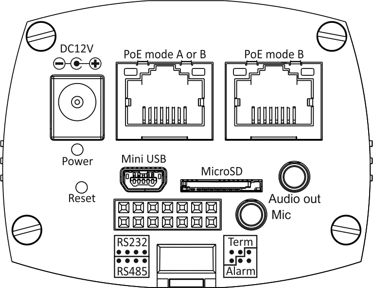
Left to right, downward:
“DC12V”: 12 V direct current power socket, + in the middle.
“PoE mode B”: PoE Ethernet socket
Both sockets are interconnected through a PoE Ethernet switch.
“Power”: LED power indicator
“Mini USB”: socket for USB 2.0 cable
“MicroSD”: socket for Micro SD cards
“Audio out”: linear audio output
“Reset”: hidden software reset button
Rectangular 14-contact socket (described below)
“Mic”: microphone input
1.3.1.1. Back panel socket SG-1C-1*1
Socket at the camera rear panel <rear-view>:
Socket pinout:
01 02 03 04 05 06 07 08 09 10 11 12 13 14
Pin description:
01,02,03,04 - RS-232 DTE port, for weather-proof housing management:
Connector pin
RS-232 signal
01
02
03
04
+12 V
- Note:
Onto the camera connector pin 04, power supply voltage +12 V is fed, which is used at the controller side as a power-supply source for optical coupler of the interface halvanic isolation.
The default parameters of the port are 9600 baud, 8N1
The device file in the camera is /dev/ttyS0
08,09,10 - RS-485 port for weather-proof housing management:
Connector pin
RS-485 signal
08
D+
09
D-
10
GND
11
+12 V
- Note:
Power supply voltage +12 V is fed to the camera connector pin 11 which does not belong to RS-485.
The device file in the camera is /dev/ttyS0
- Note:
Both ports for managing weather-proof housing are in fact one and the same port with the switchable modes RS-232 and RS-485 selected through software.
The ports can only be used one at a time, by setting the UART to the corresponding mode in the Device –> General pad through the pop-down menu “serial port type”.
05,06,12 - RS-232 DCE port for console:
Connector pin
RS-232 signal
05
2
06
5
12
3
The default parameters of the port are 115200 baud, 8N1
The device file in the camera is: /dev/ttyS1
07,13,14 - alarm inputs and outputs:
Connector pin
Function
07
ALARM_IN2
13
ALARM_OUT
14
ALARM_IN1
Alarm inputs are pulled up to +3.3 V power. An input is activated by connecting to “ground”.
Alarm output is 0 V in an inactive state and 3.3 V in an active state.
1.3.3. Back panel of SG-3C-1612:
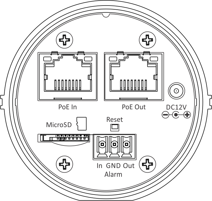
Rear panel of the SG-3C-1612 is the same as SG-3C-1312 with addition of alarm connector.
In the SG-3C-1612 camera alarm input and output are halvanically isolated by optical coupler.
Alarm input is activated by supplying voltage in range of 2..4 volts or by current 1..16 mA with external resistor.
Optical coupler input is sequence of LED and 220 Ohm resistor.
Alarm output is open collector type. The output is short to ground when asserted. Maximum voltage is 60 V and maximum current is 400 mA.