2.3. User interface
In the left of the browser screen camera control menu is located vertically.
2.3.1. Status bar
The status bar is between the image in the top part of the screen and the control menu and shows several states of the device:
- Hostname
Shows the current name of the device (hostname). The device name can be set in the Device –> General tab.
- Network
- Shows the state of being connected to the network:
- “online” shown by the green color, or
- “offline” shown with the yellow color, the duration (in seconds) of being offline being specified in brackets.
The state of being online is determined periodically (every 5 seconds) by downloading a small file. Success of the operation defines the state.
- Image Sensor
Shows the type of image sensor.
- Firmware version
Shows the version of installed firmware.
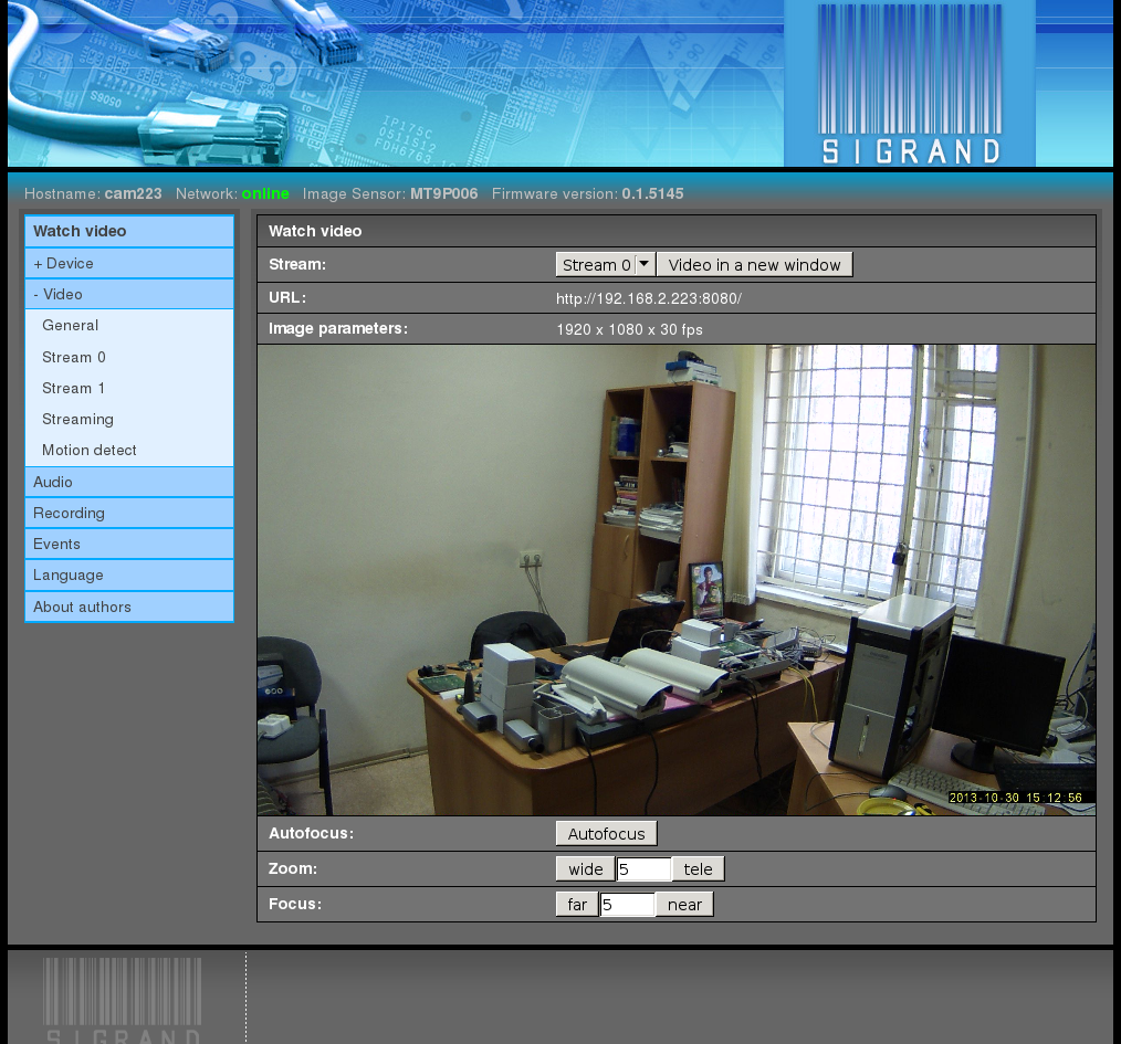
2.3.2. Watch video
The item at the very top of the menu, “Watch video”, opens by default and shows the camera video in the default format H.264 through RTSP/RTP unless other streaming formats are set:
- Note:
- The browser shows the reduced size of the image; in its initial size, the image would not fit into the screen of some monitors.
- Note:
The time lag between the real objects movement seen by the camera and the received image is about 0.25 second in case of RTSP/RTP streaming.
The browser displays the video by means of a VLC plug-in, which adds up to 2 seconds more to the delay.
For the minimum delay, use either a standalone VLC player with a “–network-caching 200” option:
vlc –network-caching 200 rtsp://camera/H264or an mplayer:
mplayer rtsp://camera/H264
2.3.2.1. Stream
The pop-down menu “Stream” selects the number of the video stream to be shown.
2.3.2.2. Video in a new window
The button “Video in a new window” opens the video in a separate new window so as not to lose the video when passing to other items in the menu.
2.3.2.3. URL
The “URL” string contains the URL through which the current video stream is received. The URL can be given to other client programs in order to make the video stream from the camera available to them.
2.3.2.4. Image parameters
This item shows the frame size (in pixels) and frame rate.
2.3.2.6. Zoom
The “Wide” and “Tele” buttons run stepper motor for a specified number of steps to change the zoom of the lens in the appropriate direction.
Works only on cameras with motorized lens.
2.3.2.7. Focus
The “Far” and “Near” buttons run stepper motor for a specified number of steps to change the focus of the lens in the appropriate direction.
Works only on cameras with motorized lens.
2.3.3. Device
2.3.3.1. General
The Device ‣ General tab shows the general parameters and settings of the device:
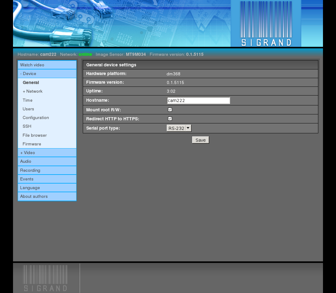
Hardware platform
It shows the version of the Texas Instruments Inc. SoC chip.
The possible values are: dm368, dmva2.
Firmware version
The version of firmware is shown.
Uptime
Shows the time of work since last boot.
Hostname
The input field for the name of the device (hostname).
The default value is “sigTIcam”.
Mount root R/W
Mounting the root file system for reading and writing.
Used for debugging.
The default value is off.
Redirect HTTP to HTTPS
Automatically redirect Web browser from the port of unprotected HTTP (80) to the port of protected HTTPS (443),
The default value is on.
Serial port type
The pop-down menu for setting the type of the serial port used in managing of a weather-proof housing or a PTZ drive.
The possible values are: RS-232, RS-485.
The default value is RS-232.
2.3.3.2. Network
The Device ‣ Network tab is used to adjust the networking settings of the device.
2.3.3.2.1. General
The Device ‣ Network ‣ General tab is used to adjust the common part of different types of network connections of the device:
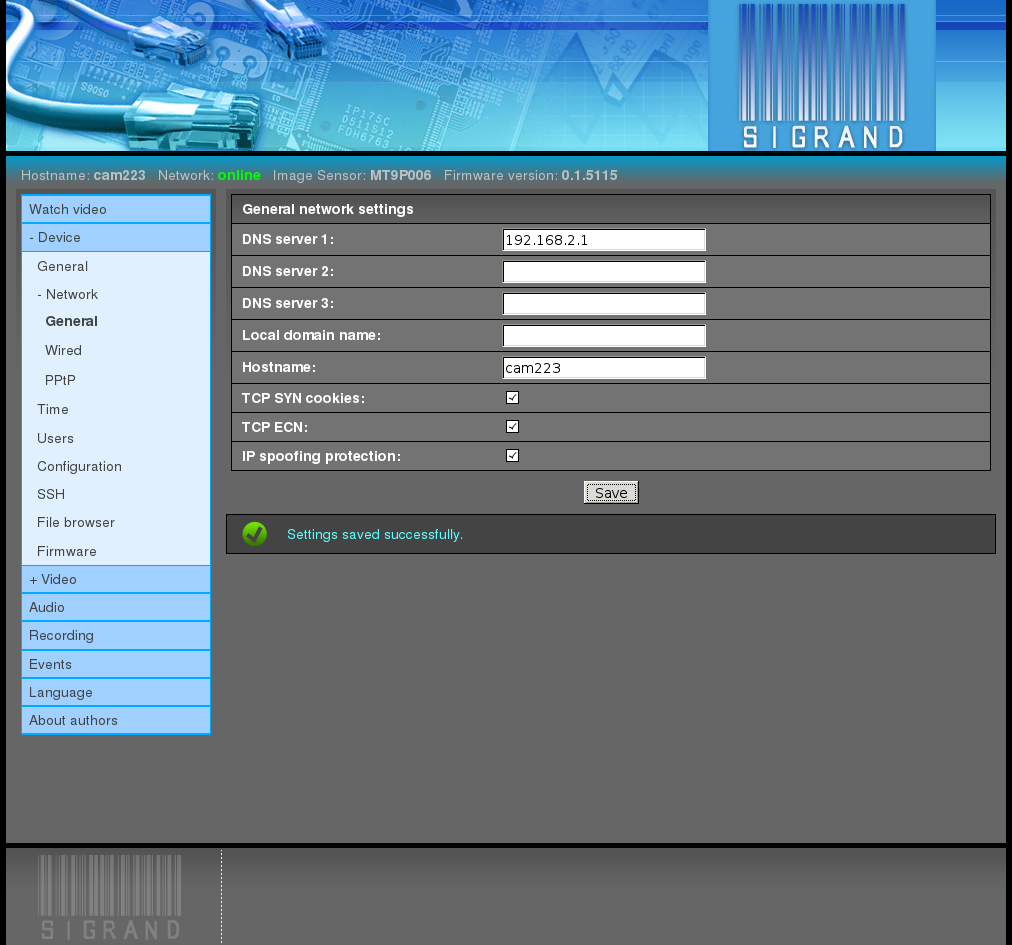
2.3.3.2.1.1. DNS server 1,2,3
In the “Name server” 1,2,3 fields, the DNS server addresses is defined.
The default value is empty.
2.3.3.2.1.2. Local domain name
The input field is value of “domain” directive of /etc/resolv.conf file.
Example: sigrand.local
The default value is empty
2.3.3.2.1.3. Hostname
The input field for the name of the device (hostname).
The default value is “sigTIcam”.
This field is the same as the one in Device –> General tab.
2.3.3.2.1.4. TCP SYN cookies
The flag “TCP SYN cookies” switches the corresponding flag (http://en.wikipedia.org/wiki/SYN_cookies) of the network stack of the device OS kernel, in order to prevent the corresponding network attack (http://en.wikipedia.org/wiki/SYN_flood).
The default value is on.
2.3.3.2.1.5. TCP ECN
The flag “TCP ECN” switches the corresponding flag (http://en.wikipedia.org/wiki/Explicit_Congestion_Notification) of the network stack of the device OS kernel.
The default value is on.
2.3.3.2.1.6. IP spoofing protection
The flag “IP spoofing protection” switches the corresponding flag (http://en.wikipedia.org/wiki/IP_spoofing) of the network stack of the device OS kernel, in order to prevent the corresponding network attack.
The default value is on.
2.3.3.2.2. Wired
The Device ‣ Network ‣ Wired tab is used to adjust the wired Ethernet connection of the device:
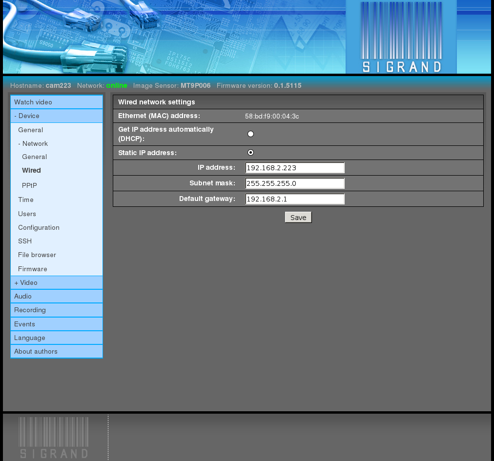
2.3.3.2.2.1. Ethernet (MAC) address
When manufactured, the device gets its unique Ethernet (MAC) address which is preserved across resetting.
Ethernet (MAC) address is stored in a file on configuration partition and is supplied with no special protection against loss or corruption, just as all the other configuration files.
The default value is 00:00:11:22:33:44.
2.3.3.2.2.2. Get IP address automatically (DHCP)
The flag permitting to get the IP address automatically through the DHCP.
Depends on availability of a DHCP server in the network and on the servers settings. If the configuration of the DHCP server does not provide that a fixed IP address should be assigned to this Ethernet (MAC) address, in most cases a vacant pseudo-random address selected from the corresponding address pool will be assigned to the device.
The default value is off.
2.3.3.2.2.3. Static IP address
The flag assigning the static IP address from the field “IP address” to the network interface.
The default value is on.
2.3.3.2.2.4. IP address
The input field of “IP address”.
This address is to be assigned by hand, and it has to be unique in the network where the device is going to be used.
The default value is 192.168.2.200
2.3.3.2.2.5. Subnet mask
In the field “Subnet mask”, a mask is assigned to separate the IP address of the network node from the network address.
The default value is 255.255.255.0
2.3.3.2.2.6. Default gateway
In the field “Default gateway”, the IP address of the router is defined.
The default value is 192.168.2.1.
The field can be left blank or assigned the value 0.0.0.0.
In local networks, there is no need for a gateway; however, it can be useful for the following purposes:
2.3.3.3. Time
The Device ‣ Time tab opens an interface for setting time synchronization of the device:
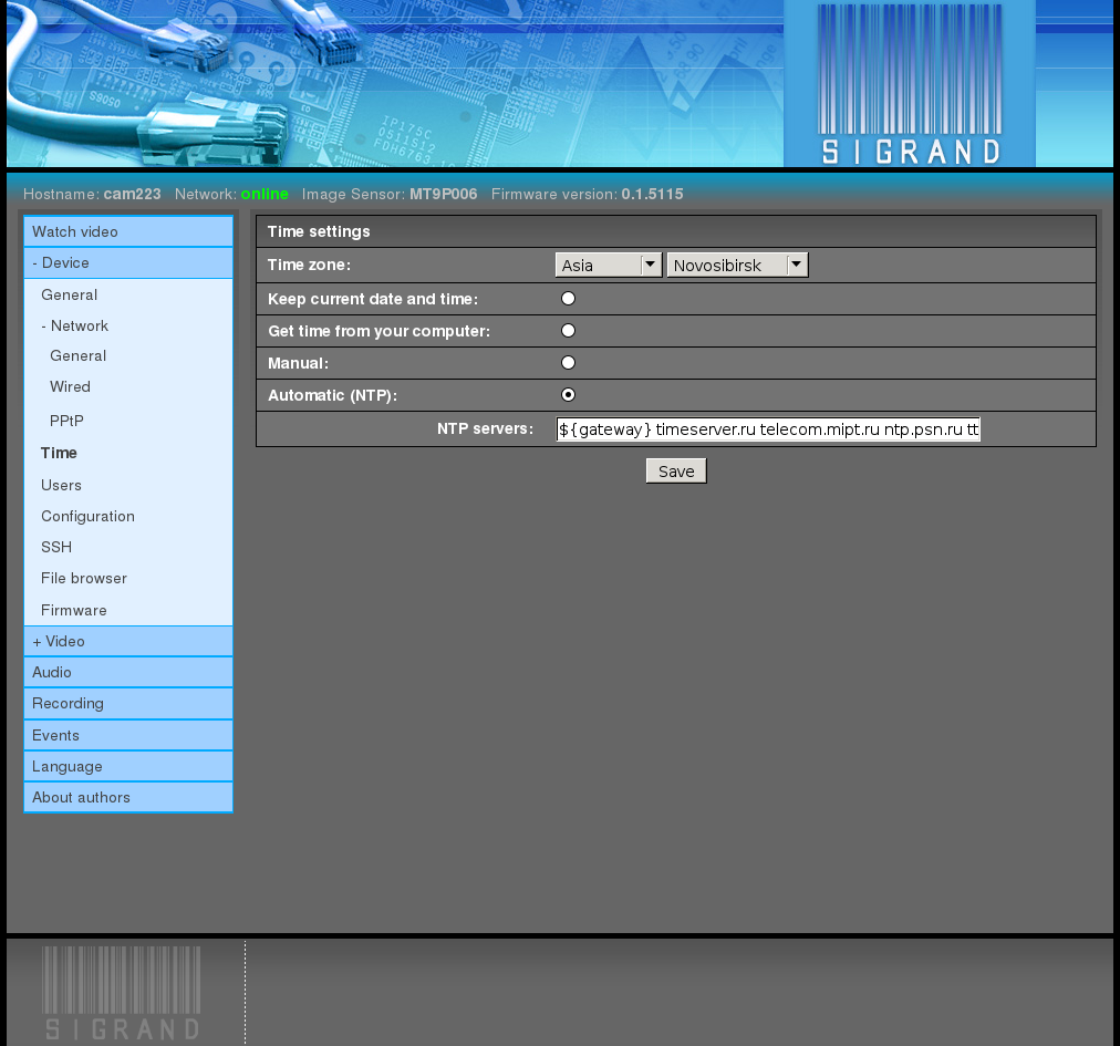
2.3.3.3.1. Time zone
The pop-down menus “Time zone” selects the time shift of the local time against the Universal Time Coordinated (UTC)
The default value is Asia/Novosibirsk.
2.3.3.3.2. Mutually exclusive flags
Keep current date and time:
No time manipulations are performed
Synchronize with your computer time
Manual
Time is set by entering it manually
Automatic (NTP)
An NTP daemon works at the device constantly synchronizing time from the NTP servers specified below.
The default value is automatically (NTP).
2.3.3.3.3. NTP servers
The input field “NTP servers” contains a list of time servers names.
The default value is “${gateway} timeserver.ru telecom.mipt.ru ntp.psn.ru ttm.chant.ru”.
- Note:
- The first server ${gateway} is a reference to the variable containing “Default gateway”. In case there is an NTP server established at the gateway, the device will get time synchronization from the server.
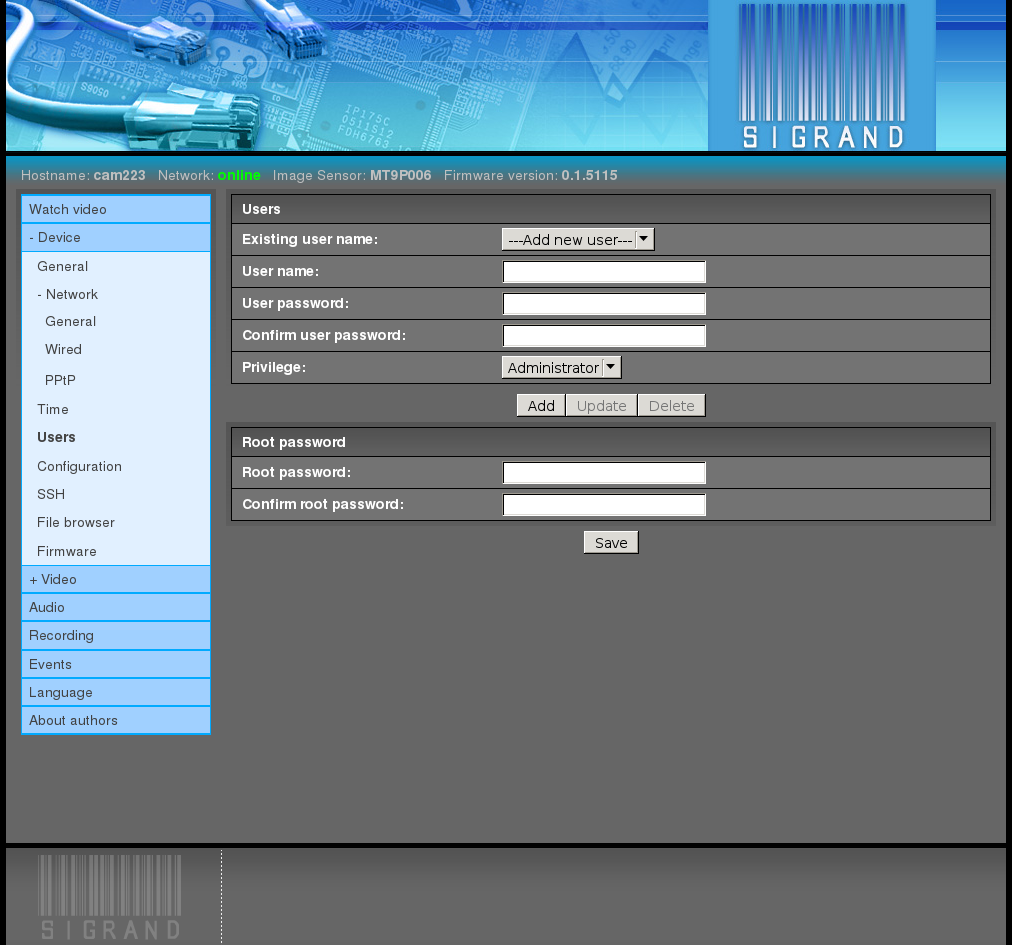
2.3.3.4. Users
The Device ‣ Users tab is used for adjusting users settings. It gives the possibility to change the Web admin password, add new Web users, and change the password of the OS superuser (root):
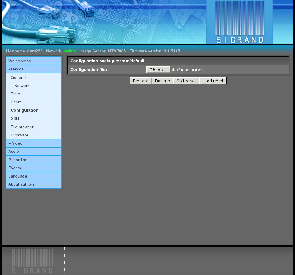
2.3.3.5. Configuration
The Device ‣ Configuration tab is used to save the current configuration of the device to a file at the file system of the PC which run browser, to restore the device configuration from the file, and to reset the configuration:
2.3.3.6. SSH
You can use the Device ‣ SSH tab to add users public keys so that access through the SSH protocol will proceed without entering a password.
If you do not have a public key, you can create it with a command in a user shell of your computer:
ssh-keygen -t rsa
Generating public/private rsa key pair.
Enter file in which to save the key (/home/tst/.ssh/id_rsa):
Created directory '/home/tst/.ssh'.
Enter passphrase (empty for no passphrase):
Enter same passphrase again:
Your identification has been saved in /home/tst/.ssh/id_rsa.
Your public key has been saved in /home/tst/.ssh/id_rsa.pub.
The key fingerprint is:
0f:b3:a2:cf:6e:98:a3:c3:e1:51:30:9a:86:be:fc:02 tst@dfsig
The key's randomart image is:
+--[ RSA 2048]----+
|                 |
|  o              |
|.o o             |
|+.  .            |
|o  .    S        |
|E.o      =       |
|oo.o o. . .      |
| ++ +o..         |
|  ++.=+          |
+-----------------+
Then output the created key .. code-block:: sh
cat $HOME/.ssh/id_rsa.pub
ssh-rsa AAAAB3NzaC1yc2EAAAADAQABAAABAQDVQbG8+dxn/bmAZmNrYc+Mqs
QeL11bX2h3UkH9uAeUssw2czQxSryHdQZaRgdCliFPdq07NYB1pQxWDcX2ES3C
wv6g2lsHQyHmvrxcxFmxYQ/U9LtW7fk/5Ad2piSJkvKQgbxU4uvFnHlBT0y0Kl
Zhd3wd5STEWMF2q9FORpROMZz9pb/ALnCQgSXjEBJRcrq8fwu74t+E/5P1n8If
2+1Vwk1v+Gen71O6xvcWICmPPs/QO/twGOA6cVmFHg4+Ag91yoC2+jCU4kQhjm
lVuaUSRCL2UWhltJJjRCXkdf+jJgfN1WhJjsMoSizH1u6fC1ju1B12C2gqn73m
qVPTc9Jn tst@sigrand
and select it with a triple click of the left mouse button. Insert the selected fragment into the field “SSH key” by clicking the middle button of the mouse:
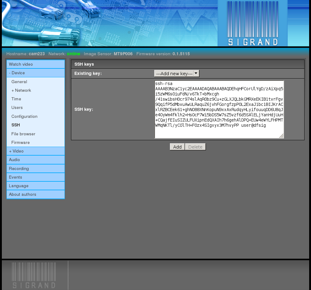
and press the button “Add”. Note:
If the operating system used at your computer is Microsoft Windows, then you can make use of one of the SSH client programs for Windows:
PuTTY, SecureCRT, ShellGuard, Axessh, ZOC, SSHWindows, ProSSHD, or XShell
and the routine of creating keys will be different.
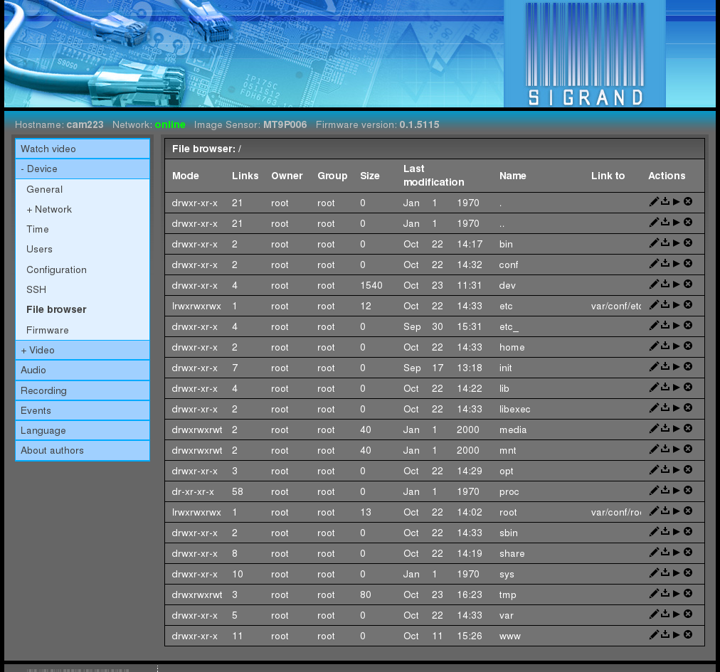
2.3.3.7. File browser
The Device ‣ File browser tab can be used to view the list of files of the mounted file systems of the device, view and edit files, save a device file to the computer where the Web browser is started, start or remove a file:
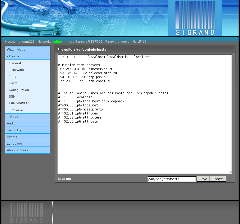
View/edit file /etc/hosts:
2.3.3.8. Firmware
The Device ‣ Firmware tab is used to update the firmware of the device.
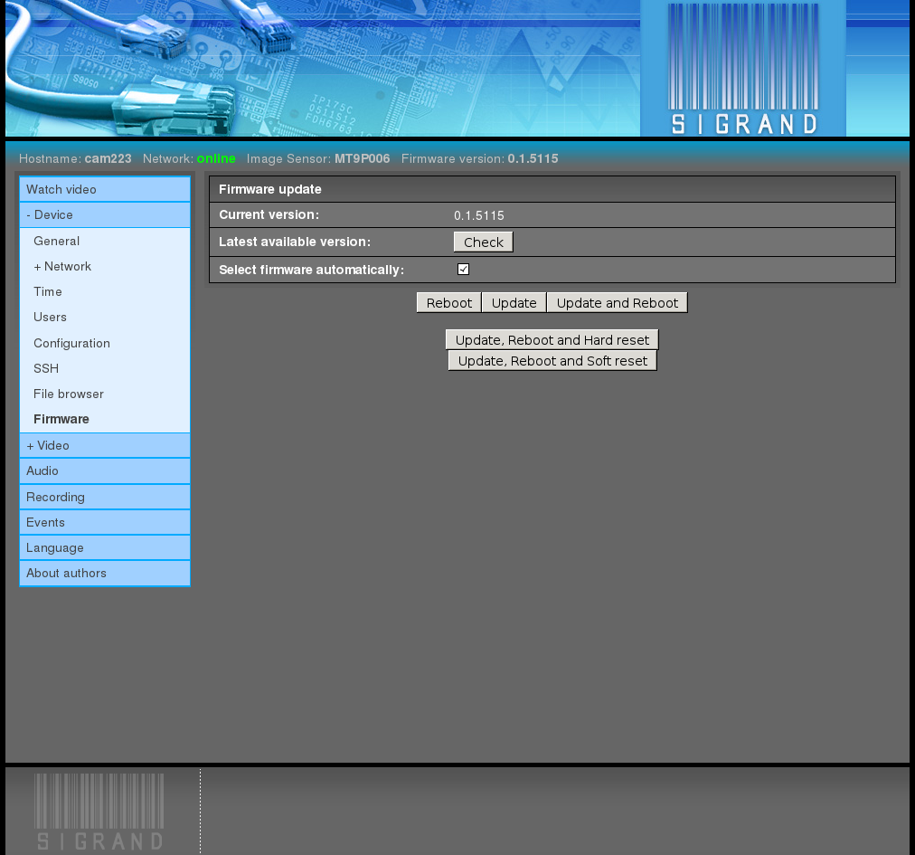
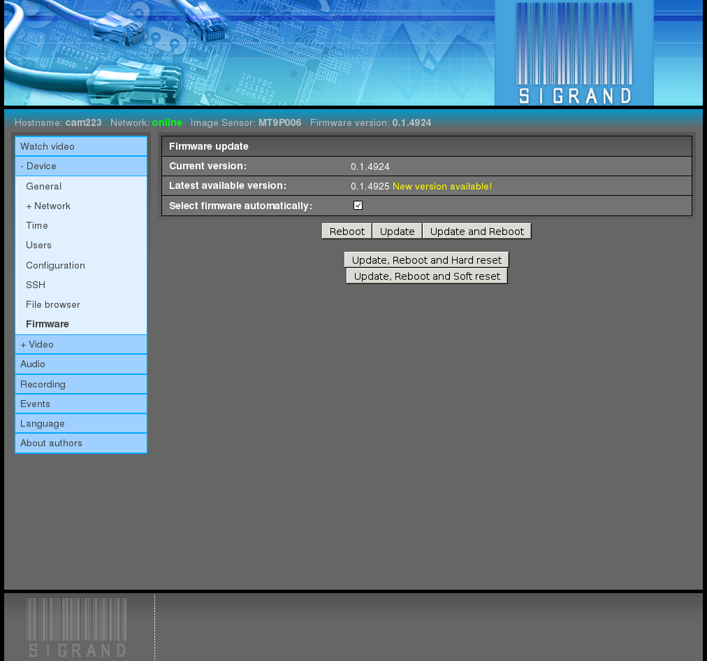
The “Check” button checks availability of a new firmware version at the manufacturer site, if the camera has access to the Internet.
If the latest version at the manufacturer site is newer than current one, a message “New version available!” is shown.
If access to the Internet is not available, you can update the firmware from your PC by unchecking the box “Select firmware automatically” and choosing a firmware update file by the “Browse” button. The file should be downloaded beforehand from the manufacturer site.
The firmware update files are published at the site of the device manufacturer http://sigrand.ru/dl/camera/ti/firmware and have the following form: sigticam-<platform>-<version>.tar.
After choosing the firmware update file,
click the button “Update and Reboot”:
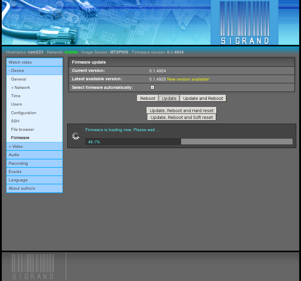
It takes up to 90 seconds to perform reboot with firmware update.
2.3.4. Video
2.3.4.1. General
The Video ‣ General tab adjusts the general video parameters:
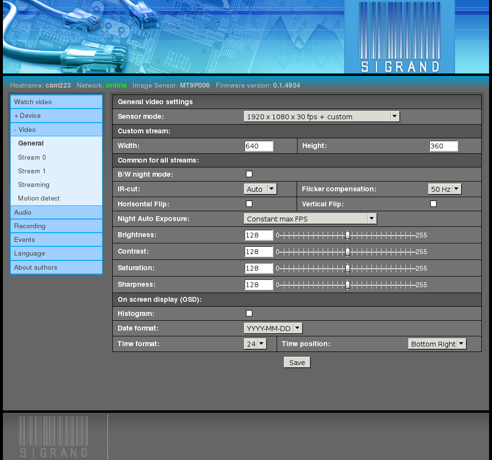
2.3.4.1.1. Sensor mode
The pop-down menu “Sensor mode” defines the image sensor mode and at the same time parameters of the second and third video streams.
The default value depends on the type of the image sensor: 1920 x 1080 for AR0331 and MT9P006, 1280 x 720 for MT9M034.
2.3.4.1.2. Custom stream
The input fields “Width” and “Height” for parameters of the second stream if it is enabled by “Sensor mode”.
The default values is 640 x 360.
2.3.4.1.3. B/W night mode
Enables automatic Black-White mode al low light condition (at night).
2.3.4.1.4. IR-cut
The pop-down menu “IR-cut” selects the mode of the IR filter:
Auto
The filter opens automatically in a low light condition (at night) and closed in a high light condition (in the daytime).
Close
The filter is always closed.
Open
The filter is always opened.
2.3.4.1.5. Flicker compensation
The pop-down menu “Flicker compensation” is used to set the feeding current frequency for the illuminating lamps which create the effect of the image flickering.
The possible values are:
No
No flicker compensation is made
50 Hz
Flicker compensation is made for the lamps fed by 50-Hz current
60 Hz
Flicker compensation is made for the lamps fed by 60-Hz current
2.3.4.1.6. Horizontal Flip; Vertical Flip
The flags of horizontal and vertical mirroring are used to switch on rotatory reflection round the horizontal and vertical axis, respectively.
The feature is useful when the camera is fixed in a wrong position.
2.3.4.1.7. Night Auto Exposure
The pop-down menu “Night Auto Exposure:” is used to select priorities for the automatic exposure algorithm.
The possible values are:
Constant max FPS
In this case, intensity of illumination is maintained through intensification, with the frame rate being kept to the utmost at the prescribed level.
Variable FPS from max to half of max
In this case, intensity of illumination is maintained by increasing exposure at the expense of the frame rate up to half of max FPS
Constant 5 FPS
2.3.4.1.8. Brightness, Contrast, Saturation, Sharpness
You can use the input fields and graphic slider bars to adjust the corresponding parameters.
The range of values is 0 .. 255.
The default value is 128.
2.3.4.1.9. HDR mode
The flag “HDR mode” is used to switch on the High Dynamic Range (HDR) mode when several pre-frames of the object taken with various exposures are superposed to produce a single fully-featured high-quality frame of natural contrast and color grade.
This feature allows surveillance in a complicated environment, for instance, when the site of surveillance gets alternately in the sun and in the shade, or when the camera is spotlighted with directional glaring light.
The “HDR mode” is presented only for image sensors MT9M034 and AR0331.
Adaptive Local Tone Mapping It is recommended to turn on this parameter in outdoor conditions or indoor with bright objects.
With high noise level indoor try turn this parameter off.
“Adaptive Local Tone Mapping” is presented only for image sensor AR0331.
2.3.4.1.10. Histogram
When the flag “Histogram” is switched on, the histogram is displayed in the left bottom corner, superimposed over the video.
2.3.4.1.11. Date format
The pop-down menu “Date format” selects the format of displaying data in the video stream.
The possible values are:
- DD.MM.YYYY
- MM/DD/YYYY
- YYYY-MM-DD
The default value is YYYY-MM-DD
where:
- DD is the day of the month, 1..31
- MM is the number of the month, 1..12
- YYYY: year, 4 digits
2.3.4.1.12. Time format
The pop-down menu “Time format” selects the format of displaying time in the video.
The possible values are:
- 12
- 24
The default value is 24.
2.3.4.1.13. Date and Time position
The pop-down menu “Date and Time position” defines where to display the date and time.
The possible values are:
- Bottom Right
- Bottom Left
The default value is Bottom Right
2.3.4.2. Stream N
The Video ‣ Stream N tabs, where N is the stream number 0,1, show the settings for the video streams; the size of their images is selected in the settings of image sensor mode:
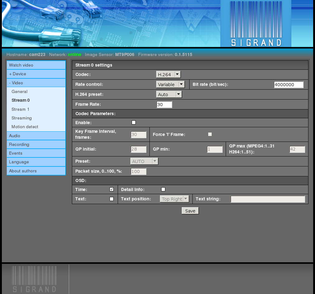
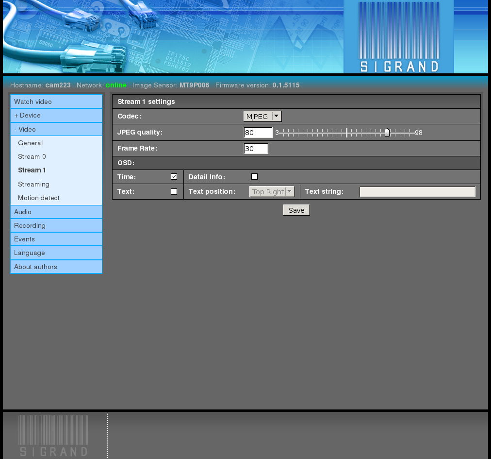
2.3.4.2.1. Codec
The pop-down menu “Codec” is used to set the codec type for the current stream.
The possible values are:
2.3.4.2.2. Rate control
The pop-down menu “Rate control” selects the compression mode of MPEG-4 and H.264 codecs:
2.3.4.2.3. Bitrate
The input field “Bittate” is used to adjust the compression parameter for MPEG-4 and H.264 codecs, bits per second.
The range of values is 2.000.000 .. 12.000.000.
Values below 512.000 are also possible but not recommended.
2.3.4.2.4. JPEG quality
The input field and graphic slider bar “JPEG quality” are used to adjust the image quality / compression degree parameter for JPEG frames.
The range of values is 3..98
The default value is 75.
The higher the value, the better the image quality, and the lower the compression degree, and the larger the frame size.
2.3.4.2.5. Frame rate
In the field “Frame rate”, frames-per-second rate of the stream is defined.
The specified frame rate of the stream is provided by frame skipping.
The default value is 30.
2.3.4.2.6. Codec parameters
The flag “Enable” is used to enable the codec parameters block described below.
The default value is Off.
2.3.4.2.7. Key frame interval
The interval (the number of frames) is defined after which the key frame is repeated.
The default value is 30.
2.3.4.2.8. Force ‘I’ frame
Codec does not create P- and B-frames, only I.
The default value is Off.
2.3.4.2.9. QP initial, min, max
The input field for entering the initial, minimum, and maximum values of the codec Quantization Parameter (QP).
The range of values is 1..31 for MPEG-4 codec and 1..51 for H.264 codec.
2.3.4.2.10. Preset
The pop-down menu “Preset”.
The possible values are AUTO, CUSTOM, SVC.
The default value is AUTO.
2.3.4.2.11. Packet size
In the field “Packet size”, the packet size is defined in terms of percentage.
2.3.4.2.12. Time
When the flag “Time” is switched on, the current local time and date is displayed, superimposed on the current video stream.
2.3.4.2.13. Detail info
When the flag “Detail info” is switched on, the detailed information on the video stream is displayed, superimposed over the image.
2.3.4.2.14. Text
When the flag “Text” is switched on, a users text line is displayed over the video.
2.3.4.2.15. Text position
The pop-down menu “Text position” defines where to display the users text line:
- Top right
- Top left
2.3.4.2.16. Text string
In the input field “Text string”, you can enter a users text line.
The length of the line must not exceed 23 printed 7-bit ASCII characters from the following set:
A-Za-z:; '/\+-_()&$#.0123456789
In order to prevent falling down of the camera audio/video server, characters outside this set will be substituted as follows:
- % to space
- Double quote ‘ ” ‘ to single quote ” ‘ “
- Others to #
Extra symbols (in the positions after 23) are cut off.
2.3.4.3. Streaming
The “Streaming” tab configures different modes of video and audio streaming:
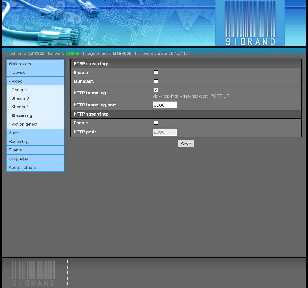
2.3.4.3.1. RTSP streaming
2.3.4.3.1.2. Multicast
The “Multicast” checkbox turns on the mode of group transfer of media stream.
Multicast streaming greatly reduces the traffic in case of multiple clients.
2.3.4.3.1.3. HTTP tunneling
The “HTTP Tunneling” checkbox turns on HTTP-based tunneling mode of packet streaming.
It is useful for bypassing restrictions of the Internet provider.
2.3.4.3.2. HTTP streaming
HTTP streaming is currently available only for silent video encoded by MJPEG.
- Note:
- Video streaming in MJPEG format through HTTP is fully supported by such browsers as Mozilla Firefox, Iceweasel, Google Chrome, and to no extent by Microsoft Internet Explorer and Opera.
2.3.4.3.2.2. HTTP port
The “HTTP port” input field specifies a port for the HTTP streaming server of the camera.
Default setting: 8080.
2.3.4.4. Motion detect
The “Motion detect” tab manages the motion detector settings:
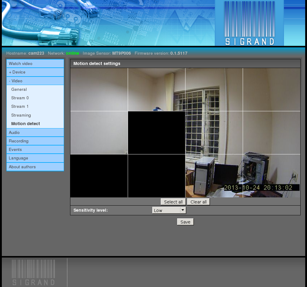
The window contains a picture from the camera updated every 5 seconds.
To obtain the picture, select the JPEG codec for one of streams.
The window is partitioned into 12 equal rectangulars, defining sensitive areas of the motion detector.
By a left click of the mouse corresponding area is turned on or off.
Disabled areas do not take part in motion detection.
The changes are activated by pressing the “Save” button.
2.3.4.4.1. Select all
The “Select All” button turns on all motion detector areas.
2.3.4.4.2. Clear all
The “Clear all” button turns off all motion detector areas.
2.3.4.4.3. Sensitivity level
The “Sensitivity level” pulldown menu changes the motion detector sensitivity:
- Low
- Medium
- High
2.3.5. Audio
The Audio tab is used for adjusting the audio subsystem of the device:
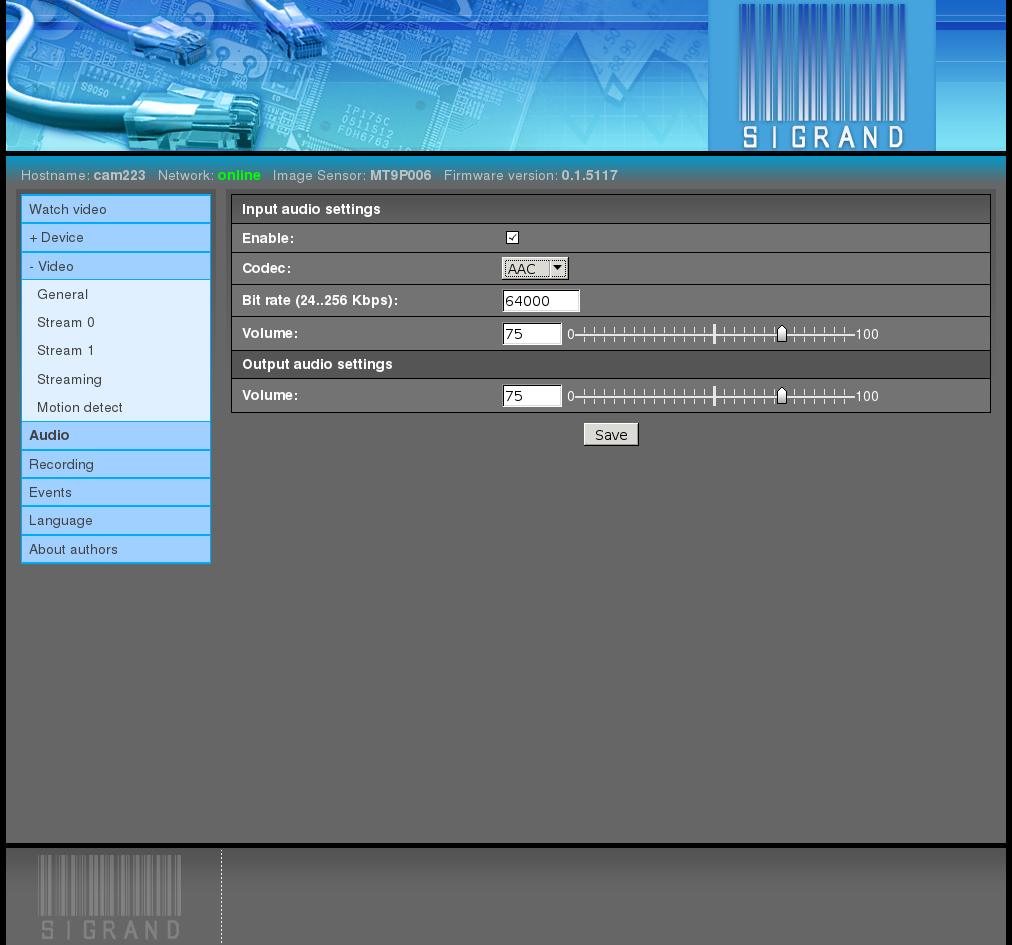
2.3.5.1. Enable
The flag “Enable” switches on the audio subsystem of the device and enables the other audio settings.
2.3.5.2. Audio codec
The pop-down menu “Audio codec” is used to select one of the two supported audio codecs:
- G.711
- Sampling frequency: 8 KHz
- Bitrate: 64 Kbits per second
- AAC
- Sampling frequency: 8 KHz
- Bitrate: 24..128 Kbits per second
2.3.5.3. Audio bitrate
The input field “Audio bitrate” is used to select the stream bitrate.
For G.711 codec, the only possible value is 64000.
For AAC codec, the range of values is 24000..128000.
2.3.5.4. Input and Output volume
The input fields and graphic slider bars “Input volume” and “Output volume” are used to set the values of the corresponding regulators of the hardware mixer.
The range of values is 0..100.
The default value is 75.
- Note:
- The regulators of the hardware mixer may have rougher level scales.
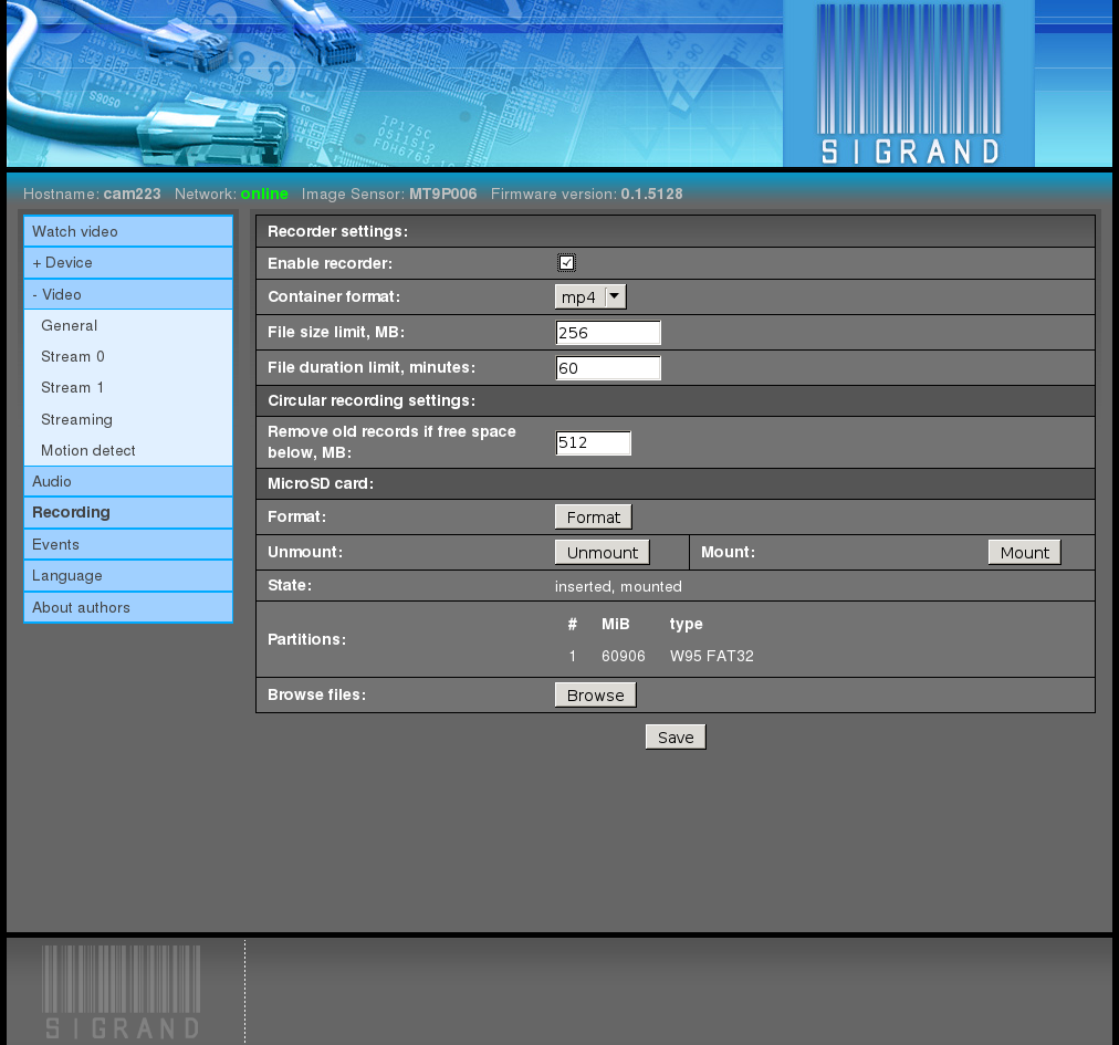
2.3.6. Recording
The “Recording” tab manages video and audio recording to files on the Micro SD card:
Recorded files have user-defined time and size limits.
Upon reaching the limit the file is written with several frames until a keyframe is found, whereupon the file is closed. Then a new file opens and begins with the last keyframe.
Thus, subsequent files have a one-frame overlap and always begin with a keyframe.
Files have names derived from their start time in the local timezone:
YYYY-MM-DD_hh-mm-ss-msc.ext
- where:
- YYYY - year
- MM - month number
- DD - day of month
- hh - hours
- mm - munutes
- ss - seconds
- msc - milliseconds
- ext - choosen file extension
- For examle:
- 2013-10-25_19-25-33-153.mp4
2.3.6.1. Enable recorder
The “Enable recorder” checkbox enables video and audio recording.
2.3.6.2. Container format
The “Container format” pulldown menu chooses the format of a media file.
The list of available formats depends on the combination of selected video and audio codecs.
Default value: mp4.
2.3.6.3. File size limit
The “File Size Limit” input field specifies the maximum media file size in MiB.
Default value: 256.
Since the SD Card is formatted in FAT32, the file size limit is 4 GiB.
It is recommended to specify the size less than 4096 MiB with a good margin, because upon reaching the limit a few frames more and a format-defined “tail” are written.
If the file reaches the 4096 MiB limit, it is forcedly closed by the filesystem, and the recording process stops and does not restart automatically.
2.3.6.4. File duration limit
The “File duration limit” input field specifies the maximum duration of the recorded media file in minutes.
Default value: 60.
2.3.6.5. Circular recording
To avoid halting of the recording process caused by an SD Card overflow, when the free space decreases below the specified limit, the oldest files are deleted.
2.3.6.6. MicroSD card
The “Micro SD card” section is intended for SD Card monitoring and managing.
2.3.6.6.1. Format
The “Format” button reinitializes the partition table of the card and makes a partition with a FAT32 filesystem.
Before the formatting the recording processes are stopped and started again after completion of the formatting.
For a 64 GB card the formatting takes 2 to 2.5 minutes.
2.3.6.6.2. Unmount
The “Unmount” button unmounts the card filesystem, stopping the recording processes, and allows you to remove the card from the camera safely.
The other techinque of the safe card removal:
Pressing the “Reset” button on the back camera panel for 0.5-1.0 seconds.
If the card is inserted, the “Reset” button changes its function and makes unmounting of the card.
After 30-60 seconds taken for safe termination of the recording process, the card can be removed.
2.3.6.6.3. Mount
The “Mount” button mounts the card filesystem, starting the recording processes if the recording was enabled before.
The button is needed only as a complement to the “Unmount” button, because upon the insertion of the card with suitable partinion types, filesystem, and free space, the card is mounted automatically and the recording process is started, if it is enabled.
2.3.6.6.4. State
The “State” string displays the current state of the card.
Possible values are:
absent
inserted
The card is inserted into the slot, but is not mounted for some reason (unsuitable card partition or unmounted by the “Unmount” button).
inserted, mounted
The card is inserted into the slot and mounted.
2.3.6.6.5. Partitions
The “Partitions” section dispays the list of partitions of the inserted card.
Example:
# MiB type 1 60906 W95 FAT32
where:
2.3.6.6.6. Browse files
The “Browse files” button opens the file browser at the root of the card filesystem.
2.3.7. Events
The “Events” tab allows to define a reaction to incoming events:
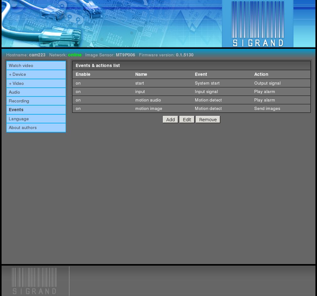
The result of the configuring is the set of rules connecting an incoming event (motion detector, input signal, system startup) to an action (output signal, alarm sound playing, sending of a picture).
2.3.7.1. Add
The “Add” button creates a new rule, opening the rules editor:
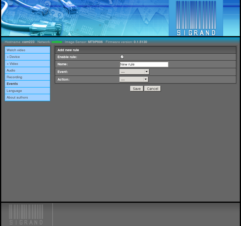
2.3.7.1.1. Enable rule
The “Enable Rule” checkbox enables the rule.
Disabling the rules allows you to save them without applying.
2.3.7.1.2. Name
The “Name” input field defines the name of the rule.
It exists only for user’s convenience and performs no function. It can be left empty.
2.3.7.1.3. Event
The “Event” pulldown list specifies one of the available incoming events:
System Start
The “System Start” event arises upon starting of the camera.
Input Signal
The “Input Signal” event arises when the corresponing pin of the back panel connector is closed to the ground.
The front of the pulse is considered as an event.
The “Input Signal Number” pulldown menu specifies one of the two available inputs, 1 (pin 14) or 2 (pin 7).
Motion Detector
The “Motion Detector” event is caused by a motion detection signal.
Note: for motion detection an MJPEG codec is required for one of streams.
2.3.7.1.4. Action
The “Action” pulldown list specifies one of the available actions:
Output Signal
A logic ‘1’ pulse (about 3.3 V) is applied to Pin 13 of the rear panel connector.
The duration of the pulse is specified in milliseconds by the “Output Signal Duration” input field.
The default state of the output signal is logic ‘0’.
Play Alarm
An alarm audio signal is applied to the (analog) line output of the camera.
Send Picture
A single JPEG frame is sent to the URL defined by the “Destination Address” input field.
scheme://user:pass@someserver.com/some/path/
where:
- scheme - “ftp” or “http” URL scheme
- user:pass - optional username and password of the server
- someserver.com - server address
- /some/path - an existing path on the server, where the file with a JPEG picture will be placed.
The file has a name derived from the time of the shot in the local timezone:
YYYY-MM-DD_hh-mm-ss-msc.jpeg
- where:
- YYYY - year
- MM - month number
- DD - day of month
- hh - hours
- mm - minutes
- ss - seconds
- msc - milliseconds
For example:
2013-10-25_19-25-33-153.jpeg
Usually a few frames are sent by a motion detection event.